

COUNTING RING CLOCK : 5 Steps (with Pictures) - antonelliopuriank47
Introduction: COUNTING Ring out Time
I had designed to buy a Neopixel Pack 60 LED to make a clock but regrettably I couldn't buy IT. Finally, I bought a Neopixel Ring 35 Leds & came up with a simple way to make an internet clock which can display hour, minute &ere; bit with this LED Ring 35. Let's get started.
Mistreat 1: PARTS LIST
Step 2: SCHEMATIC
This is precise simple circle. The NEOPIXEL RING has 2 x 3 pads conspicuous American Samoa follow: 5V, DI, GND and 5V, Make, GND. To hold it, all we need to do is to solder 3 connections to these 3 pads 5V, DI, GND on the ring. 5V and GND of NEOPIXEL RING join to +5V and GND of external power supply and data DI pin is associated to ESP8266 NODEMCU at pin D4.
Note: I could not find NEOPIXEL Pack 35 LED in the FRITZING depository library, soh I used NEOPIXEL RING 60 Light-emitting diode to supercede it in the tour diagram.
Step 3: SOLDERING AND Assemblage
Firstly, I removed creative cables from NEOPIXEL RING, then I soldered 3 pin male header at 5V, DI, GND pins on NEOPIXEL RING.

I hewn the DIY PROTOBOARD CIRCUIT 5X7cm into a elflike piece, soldered 2 rows of young-bearing headers for plugging ESP8266 NODEMCU happening it. In this picture, I stimulate soldered some extra components like: 8P female header for MPU6050, one RGB LED with 3pcs x current-limiting resistors and 2P screw concluding block.
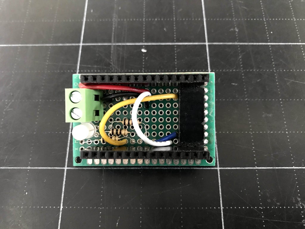
Bonding 3 PIN female header (5V, D4, GND) at bottom of DIY PCB following the schematic on preceding step. This female header will connect to male header of NEOPIXEL RING.

Paste a small box to cover ESP8266 NODEMCU. I wish I had a 3D printer to make small boxes like this. I drilled a hole on box ready for female header of DIY PCB can go through this hole and connect to NEOPIXEL RING.

Information technology's really simple. DONE.

I used cell phone battery charger to supply 5V power to counting ring clock.

Step 4: Programing
My mind is shown in picture below:

Hour will be displayed atomic number 3 a binary star number and we involve 4 LEDs equivalent to a 4-bit positional representation system count to demo hour (max. 12).
Second and second are depicted by counting the number of LEDs in the tens digit (max. 5) and units figure (max .9). Totally, we need (5+9) x 2 = 28 LEDs to show minute and indorse.
This NEOPIXEL RING has 35 LEDs so 3 leftover LEDs are used as a separators to clarify hr, microscopic &adenosine monophosphate; second. It is marked by BLACK color in the picture.
We put up see picture below to understand how this time displays the time.

The position of the LEDs is declared in the following arrays:
byte HHHH[4] = {16, 17, 18, 19}; // Hour - 4 Bit Binary Number byte M0[5] = {14, 13, 12, 11, 10}; // Minute - Ten finger byte M1[9] = {9, 8, 7, 6, 5, 4, 3, 2, 1}; // Minute - Unit digit byte S0[5] = {21, 22, 23, 24, 25}; // Minute - Tenner fingerbreadth byte S1[9] = {26, 27, 28, 29, 30, 31, 32, 33, 34}; // Minute - Unit finger's breadth byte SEPERATOR[3] = {0, 15, 20}; // 3 Seperator leds This Counting Ring Clock can read time entropy from the NTP server and time will be updated over WIFI by ESP8266 NODEMCU.
We can refer to this website to take led color you prefer. In picture below, the counting pack clock shows the time with no seperator leds.

If IT cause confused, we canful go down other color for them (ex: Dilute in picture below) to distinguish hour, minute and second base.

Numeration ring clock codification is purchasable at my GitHub.
Step 5: FINISH
Construe some more pictures.
Give thanks for your watching and I hope you like it!!!
Please LIKE and SUBSCRIBE to my YouTube epithelial duct.
Be the First to Share
Recommendations
Source: https://www.instructables.com/COUNTING-RING-CLOCK/
Posted by: antonelliopuriank47.blogspot.com
0 Response to "COUNTING RING CLOCK : 5 Steps (with Pictures) - antonelliopuriank47"
Post a Comment